Geomembrane with high tensile strength
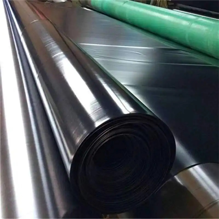
Manufacturing Process
Industrial manufacturing of geomembrane with high tensile strength follows controlled engineering steps:
Resin drying and gravimetric dosing of polymer and additives
Twin-screw extrusion compounding
Flat die or blown film extrusion forming
Online thickness monitoring by laser gauge systems
Surface texturing via embossed roller systems
Cooling by water bath or air ring systems
Automatic edge trimming and winding
Roll inspection and mechanical property testing
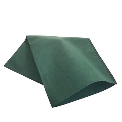
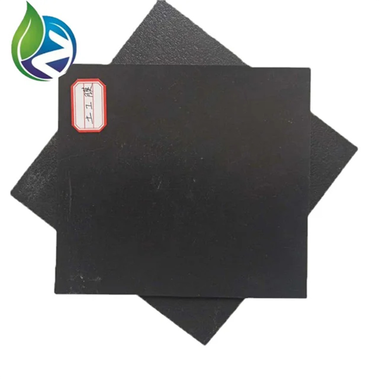
Product Definition
Geomembrane with high tensile strength is a polymer-based impermeable liner engineered to withstand high mechanical stress while providing long-term hydraulic containment, used in geotechnical and environmental engineering projects requiring superior load resistance, puncture resistance, and deformation control under complex field conditions.
Technical Parameters and Specifications
Typical technical parameters for geomembrane with high tensile strength used in industrial and civil projects are as follows:
Base polymer: HDPE, LLDPE, or reinforced PVC
Standard thickness range: 0.5 mm – 3.0 mm
Density (HDPE type): 0.94 g/cm³ – 0.96 g/cm³
Tensile strength at yield: 16–28 MPa
Tensile strength at break: 22–35 MPa
Elongation at break: 600% – 800
Puncture resistance: 600 – 1200 N
Tear resistance: 200 – 400 N
Carbon black content: 2.0% – 3.0%
Service temperature range: -40°C to +60°C
Design service life: 20 – 30 years in buried applications
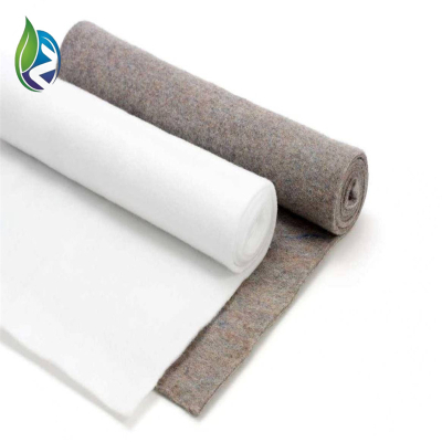
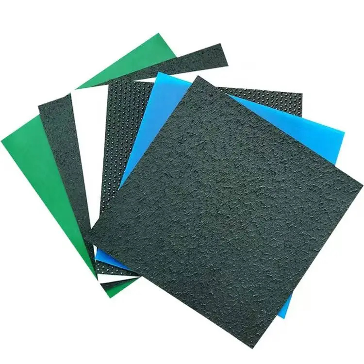
Structure and Material Composition
The geomembrane with high tensile strength adopts a multilayer structural design:
Top surface layer: UV-stabilized polymer skin
Core layer: High-density polyethylene or reinforced composite core
Reinforcement layer (optional): Polyester or glass fiber grid
Bottom layer: Anti-slip or textured functional layer
Additives: Carbon black, antioxidants, and thermal stabilizers
Manufacturing Process
Industrial manufacturing of geomembrane with high tensile strength follows controlled engineering steps:
Resin drying and gravimetric dosing of polymer and additives
Twin-screw extrusion compounding
Flat die or blown film extrusion forming
Online thickness monitoring by laser gauge systems
Surface texturing via embossed roller systems
Cooling by water bath or air ring systems
Automatic edge trimming and winding
Roll inspection and mechanical property testing
Industry Comparison
| Material Type | Tensile Strength | Puncture Resistance | Service Life | Typical Cost Level |
|---|---|---|---|---|
| Geomembrane with High Tensile Strength | High | High | 20–30 Years | Medium |
| Standard HDPE Geomembrane | Medium | Medium | 15–20 Years | Low |
| PVC Geomembrane | Low–Medium | Low | 10–15 Years | Low |
| Bituminous Liners | Low | Low | 8–12 Years | Low |
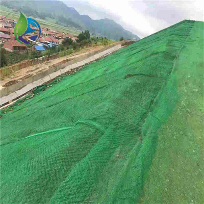
Application Scenarios
The geomembrane with high tensile strength is widely adopted by:
Distributors of geosynthetic construction materials
EPC contractors for environmental and hydraulic projects
Civil engineering contractors managing landfill and tailings projects
Infrastructure developers for water containment systems
Typical engineering uses include landfill liners, mining tailings ponds, water reservoirs, canal lining, biogas digesters, and industrial wastewater treatment ponds.
Core Pain Points and Solutions
Risk of tearing under heavy soil load — solved by using high tensile core formulations
Puncture damage from sharp aggregates — mitigated by increased thickness and protective geotextile layers
Long-term UV degradation — reduced by carbon black and UV-stabilized resin systems
Seam failure risk — addressed by automated hot wedge and extrusion welding methods
Risk Warnings and Mitigation Recommendations
Incorrect subgrade preparation may cause local stress concentration — perform ground leveling and remove sharp debris
Improper welding parameters can weaken seams — use calibrated welding equipment and real-time seam testing
Thermal expansion may generate wrinkling — install during controlled temperature windows
Incompatible chemical exposure may degrade polymer — verify chemical resistance charts before material selection
Procurement and Selection Guide
Define project hydraulic and mechanical loading requirements
Select polymer type based on chemical and temperature exposure
Determine minimum thickness according to design codes
Verify tensile and puncture test reports from accredited laboratories
Request factory quality control and traceability documentation
Confirm compatibility with available welding equipment on site
Evaluate long-term maintenance and inspection plans
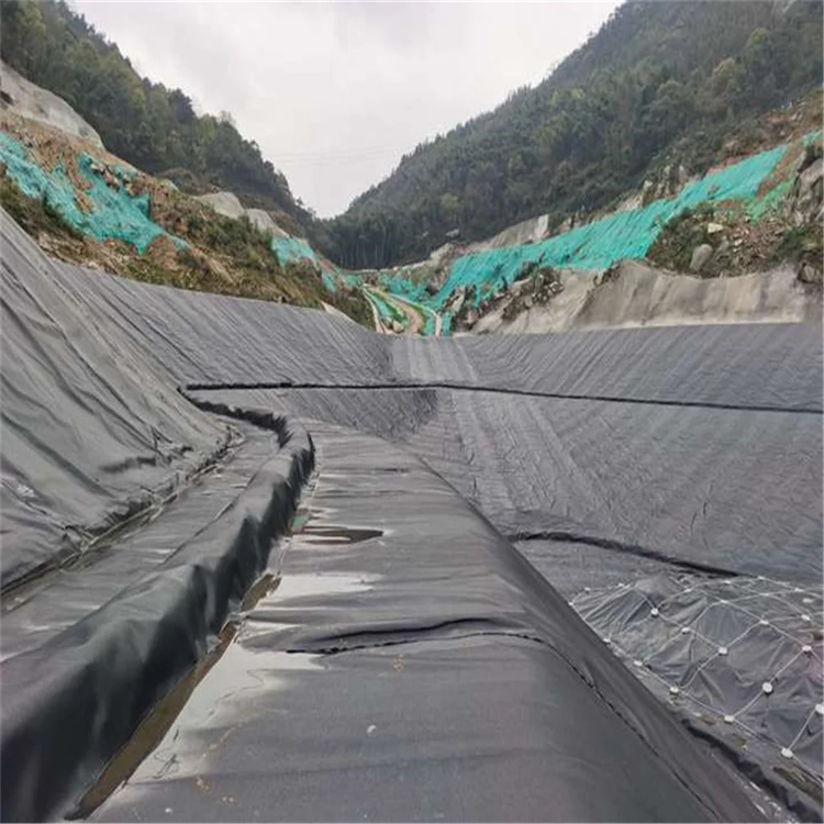
Engineering Case Example
In a mining tailings storage facility project, a geomembrane with high tensile strength with 2.0 mm thickness was installed over a compacted clay liner and nonwoven geotextile. The system covered approximately 45,000 m² and was hot wedge welded with dual-track seams. Post-installation testing showed stable tensile performance under long-term static load and improved resistance to deformation from tailings settlement.
FAQ
Q1: What tensile strength is considered high for geomembranes?
A: Typically above 20 MPa.Q2: Can the geomembrane be used in chemical ponds?
A: Yes, if chemically compatible with the fluid.Q3: What thickness is recommended for landfills?
A: Commonly 1.5–2.0 mm.Q4: How are seams tested?
A: By air pressure or vacuum box testing.Q5: Is UV resistance mandatory for buried installations?
A: Beneficial during construction and exposed phases.Q6: What is the typical roll width?
A: 5–8 meters.Q7: Can it handle differential settlement?
A: Yes, within design elongation limits.Q8: How long can it be exposed before covering?
A: Typically 2–4 weeks, depending on climate.Q9: Does it require special storage conditions?
A: Store away from direct UV and standing water.Q10: What standards govern testing?
A: ASTM and ISO geosynthetics standards.
CTA – Commercial Technical Request
For formal project procurement, request commercial quotation, detailed technical datasheets, and engineering samples of geomembrane with high tensile strength through official technical sales channels.
E-E-A-T Author Credentials
This document is prepared by geotechnical engineers and materials specialists with more than 15 years of experience in geosynthetics design, large-scale containment engineering, and international EPC project consulting, ensuring reliable technical guidance for professional B2B decision makers.


Geomembrane construction precautions:
Construction preparation: Before construction, the base surface should be levelled to ensure that no sharp objects protruded, so as not to puncture the soil diaphragm.
At the same time, the required leveling materials such as sand or clay, as well as welding equipment, should be prepared.
Laying and welding: When laying HDPE geomemofilm, it should be naturally developed to avoid excessive stretching or discounting. The two adjacent geomembranes
should be connected by thermal welding or special tape to ensure the sealing of the joints. When welding, the temperature and time should be controlled to avoid
overheating or undercooling leading to poor welding quality.
Inspection and acceptance: After the completion of construction, the HDPE geomembrane should be comprehensively inspected to ensure that it has no defects
such as damage, no bubbles, and no wrinkles. At the same time, acceptance tests, such as leakage tests, should also be carried out to ensure that its anti-seepage
performance meets the requirements.