Landfill Liner
Manufacturing Process
Raw Material Selection: Virgin polyethylene resin with stabilizers
Compounding: Addition of carbon black, antioxidants, UV inhibitors
Extrusion: Flat die or blown film extrusion to form geomembrane sheets
Surface Treatment: Optional texturing for slope stability
Thickness Control: Automated gauge and laser monitoring
Cooling and Annealing: Dimensional stabilization
Quality Testing: Mechanical, oxidative induction, permeability testing
Rolling and Packaging: Protection for transportation and storage
Product Definition
Landfill Liner is an engineered containment system designed to prevent leachate migration from municipal or hazardous waste landfills into surrounding soil and groundwater, using low-permeability materials and composite structures to meet long-term environmental protection and regulatory compliance requirements.
Technical Parameters and Specifications
Liner type: Single liner / Composite liner / Double liner system
Primary geomembrane material: HDPE / LLDPE
Geomembrane thickness: 1.0 mm – 3.0 mm
Hydraulic conductivity (geomembrane): ≤1×10⁻¹³ cm/s
Compacted clay layer permeability: ≤1×10⁻⁷ cm/s
Sheet width: 5.8 m – 8.0 m
Carbon black content: 2.0% – 3.0%
Tensile strength at yield: ≥15 MPa
Elongation at break: ≥700%
Interface friction angle (textured liner): 22° – 34°
Design service life: ≥50 years (buried condition)
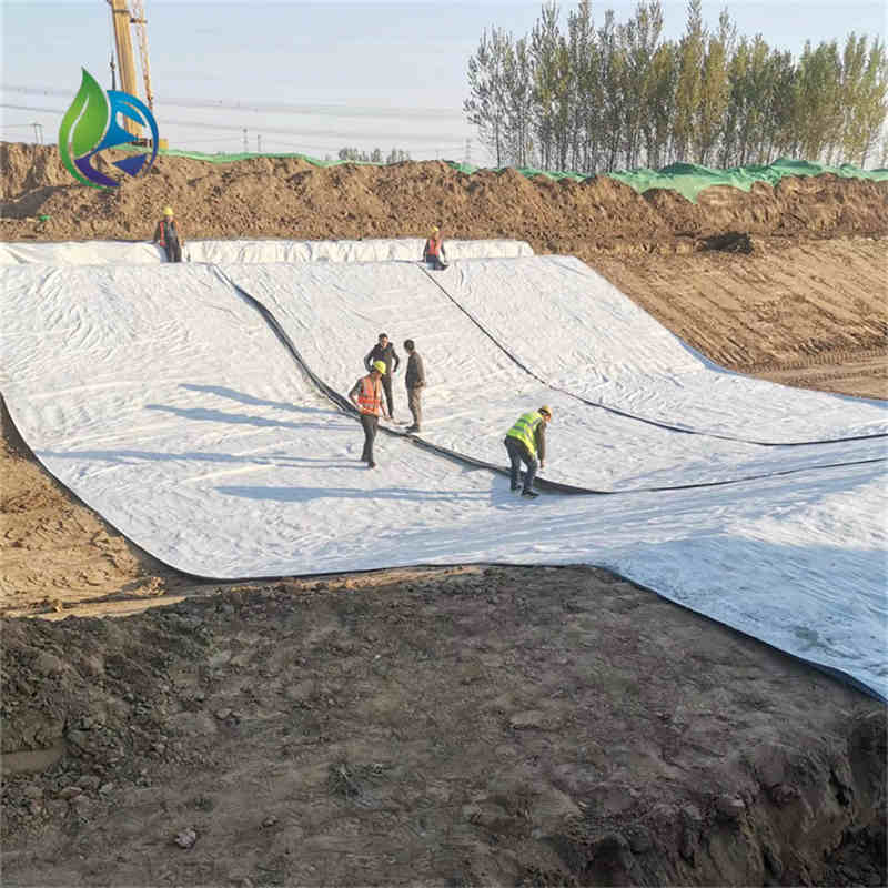
Structure and Material Composition
Waste Layer: Municipal, industrial, or hazardous waste mass
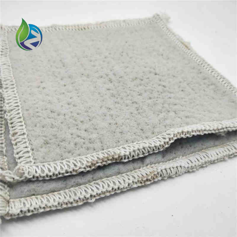
Protective Geotextile: Nonwoven fabric preventing puncture damage
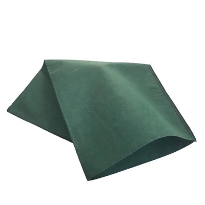
Primary Geomembrane: HDPE or LLDPE impermeable barrier
Secondary Geomembrane: Backup containment layer
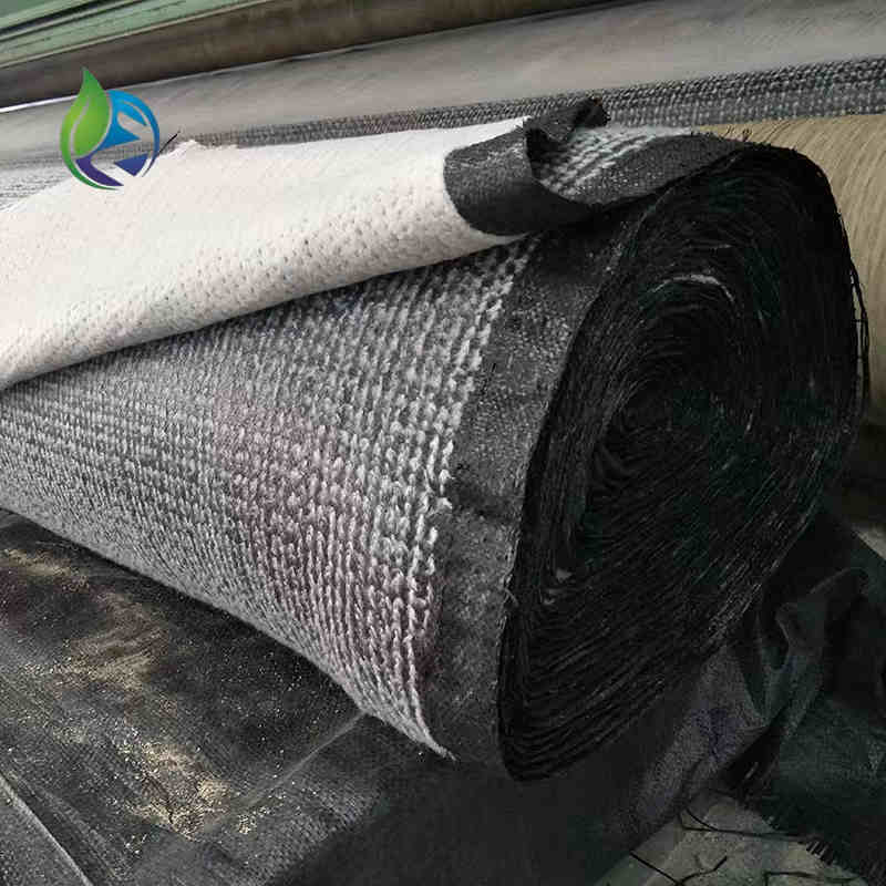
Compacted Clay or GCL: Low-permeability mineral barrier
Prepared Subgrade: Engineered foundation soil
Manufacturing Process
Raw Material Selection: Virgin polyethylene resin with stabilizers
Compounding: Addition of carbon black, antioxidants, UV inhibitors
Extrusion: Flat die or blown film extrusion to form geomembrane sheets
Surface Treatment: Optional texturing for slope stability
Thickness Control: Automated gauge and laser monitoring
Cooling and Annealing: Dimensional stabilization
Quality Testing: Mechanical, oxidative induction, permeability testing
Rolling and Packaging: Protection for transportation and storage
Industry Comparison
| Parameter | Geomembrane Liner | Compacted Clay Liner | Composite Liner |
|---|---|---|---|
| Hydraulic Performance | Excellent | Moderate | Excellent |
| Construction Consistency | High | Highly variable | High |
| Space Requirement | Minimal | Large | Moderate |
| Long-Term Reliability | High | Risk of cracking | Highest |
| Regulatory Acceptance | Widely accepted | Limited | Preferred |
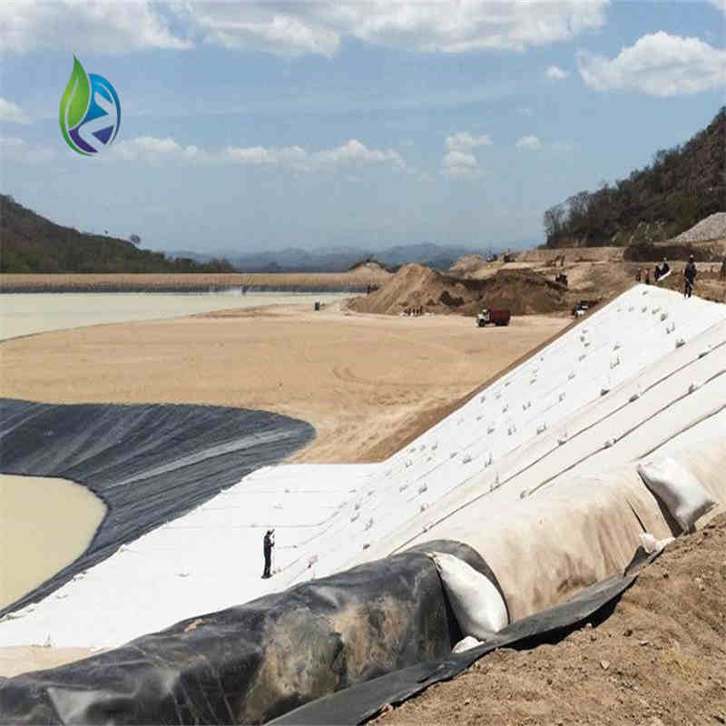
Application Scenarios
Municipal solid waste landfills
Hazardous waste disposal facilities
Industrial waste containment sites
Mining tailings and residue storage
EPC environmental protection projects
Core Pain Points and Solutions
Leachate leakage risk: Composite landfill liner systems provide redundancy
Subgrade settlement: Flexible geomembranes accommodate deformation
Slope instability: Textured liners increase interface shear strength
Long-term degradation: Stabilized polymers ensure durability over decades
Risk Warnings and Mitigation Measures
Puncture damage during installation; use protective geotextiles
Improper welding parameters; require certified welding technicians
Excessive UV exposure; limit outdoor storage duration
Inadequate quality control; implement full CQA/CQC programs
Procurement and Selection Guide
Identify waste type and regulatory requirements
Select appropriate liner system configuration
Determine geomembrane thickness based on load conditions
Specify smooth or textured surfaces for slope stability
Verify laboratory test reports and certifications
Evaluate supplier manufacturing capacity and project experience
Confirm availability of technical support and documentation
Engineering Case Study
In a municipal landfill expansion project with a design capacity exceeding 3 million cubic meters, a composite landfill liner system consisting of a 2.0 mm HDPE geomembrane and a compacted clay layer was installed. Leak detection monitoring over five years demonstrated zero measurable leachate escape, meeting stringent environmental compliance requirements.
FAQ
What is the primary function of a landfill liner? — Prevent leachate migration.
Why are composite liners preferred? — They provide redundant protection.
What thickness is commonly used? — Typically 1.5–2.5 mm for geomembranes.
Is textured liner necessary? — Required on steep slopes.
How is liner integrity tested? — Non-destructive seam testing and CQA.
What standards apply? — ASTM, GRI-GM13, and local regulations.
Can liners accommodate settlement? — Yes, polymer liners are flexible.
What is the expected lifespan? — Over 50 years when properly installed.
Is on-site welding required? — Yes, thermal fusion welding is standard.
Can landfill liners be repaired? — Localized repairs are feasible.
Call to Action
For detailed landfill liner specifications, compliance documentation, engineering consultation, or commercial quotations, please submit your project requirements to receive a professional technical response.
E-E-A-T Author Credentials
This article is prepared by environmental and geotechnical engineers with over 15 years of experience in landfill engineering, containment systems, and EPC project support, serving global contractors, consultants, and procurement teams.