Bentonite Clay Liner
Manufacturing Process
The industrial production process of Bentonite Clay Liner follows controlled engineering steps:
Raw sodium bentonite drying and particle size classification
Automated dosing and uniform distribution on carrier geotextile
Needle punching or stitch-bonding to mechanically encapsulate bentonite
Calendering under controlled pressure to stabilize thickness
Optional polyethylene film lamination
Inline quality inspection for mass per unit area and uniformity
Roll cutting, wrapping, labeling, and traceability marking
Product Definition
Bentonite Clay Liner is a low-permeability geosynthetic barrier system that utilizes sodium bentonite’s swelling and self-sealing properties to form an engineered hydraulic barrier, widely applied in containment and environmental protection projects requiring long-term groundwater and leachate control.
Technical Parameters and Specifications
Standard engineering specifications for Bentonite Clay Liner in infrastructure and environmental projects:
Core material: Sodium bentonite clay
Mass per unit area: 4.0 – 6.0 kg/m²
Hydraulic conductivity: ≤ 5 × 10⁻¹¹ m/s
Free swell index: 20 – 30 mL/2g
Moisture content: 10% – 15%
Peel strength (textile layers): ≥ 50 N/100 mm
Internal shear strength: 20 – 35 kPa
Service temperature range: -30°C to +60°C
Chemical resistance: Suitable for mild acids, alkalis, and salts
Design service life: 20 – 40 years in buried conditions
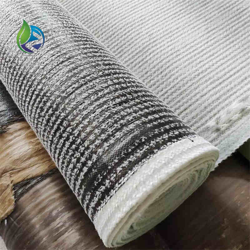
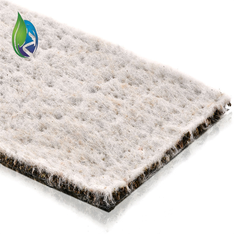
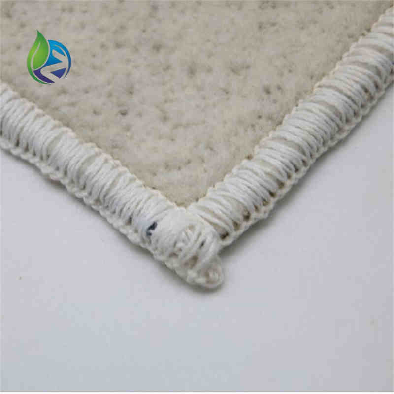
Structure and Material Composition
The layered structure of Bentonite Clay Liner typically consists of:
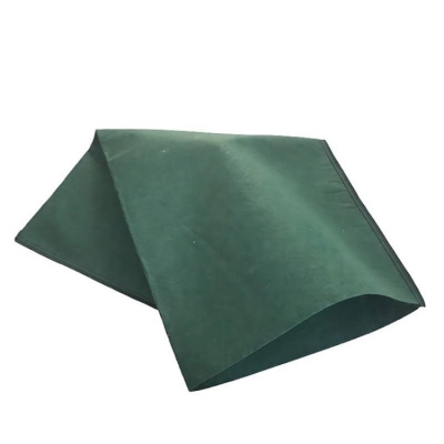
Upper layer: Nonwoven polypropylene geotextile
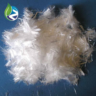
Core layer: Uniformly distributed sodium bentonite granules or powder
Lower layer: Woven or nonwoven geotextile backing fabric
Reinforcement method: Needle-punched or stitch-bonded fiber structure
Optional laminate: HDPE film coating for composite containment systems
Manufacturing Process
The industrial production process of Bentonite Clay Liner follows controlled engineering steps:
Raw sodium bentonite drying and particle size classification
Automated dosing and uniform distribution on carrier geotextile
Needle punching or stitch-bonding to mechanically encapsulate bentonite
Calendering under controlled pressure to stabilize thickness
Optional polyethylene film lamination
Inline quality inspection for mass per unit area and uniformity
Roll cutting, wrapping, labeling, and traceability marking
Industry Comparison
| Liner Type | Permeability | Self-Sealing Ability | Installation Complexity | Typical Service Life |
|---|---|---|---|---|
| Bentonite Clay Liner | Very Low | Excellent | Low | 20–40 Years |
| HDPE Geomembrane | Extremely Low | None | High | 25–30 Years |
| Compacted Clay Liner | Low | Limited | High | 15–25 Years |
| PVC Liner | Low | None | Medium | 10–15 Years |
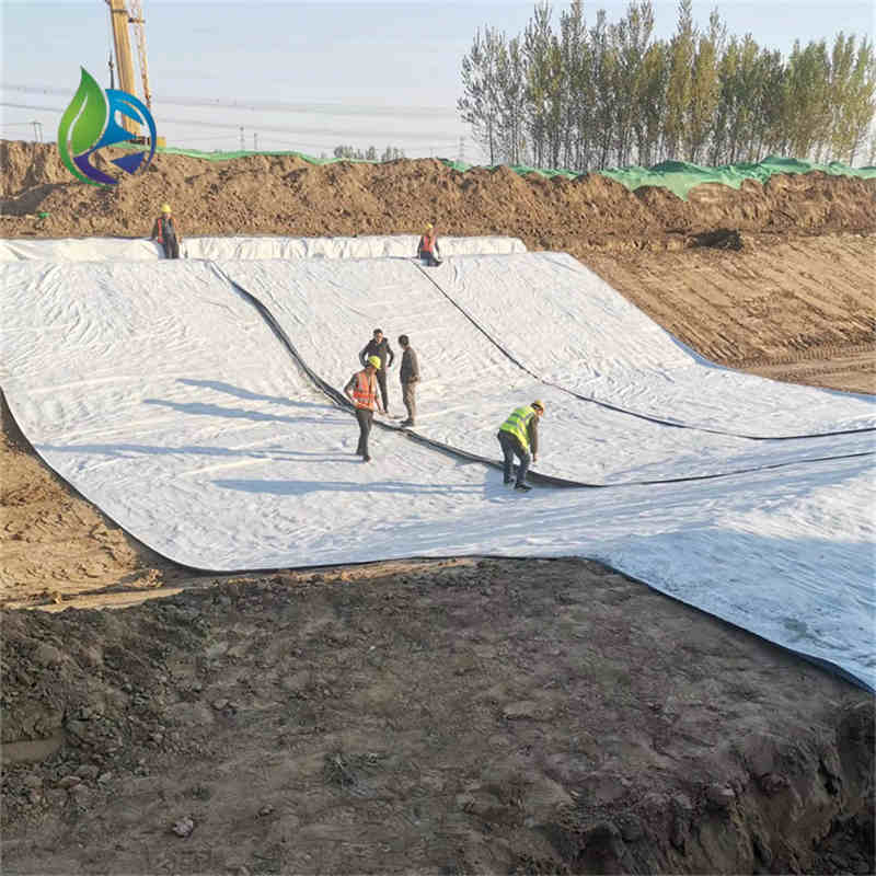
Application Scenarios
Bentonite Clay Liner is specified by:
Geosynthetics distributors servicing environmental construction markets
EPC contractors executing landfill and mining containment systems
Civil engineering firms responsible for groundwater protection design
Industrial owners developing wastewater and hazardous waste facilities
Engineering uses include landfill base liners, capping systems, decorative and industrial ponds, canals, secondary containment zones, and foundation waterproofing works.
Core Pain Points and Solutions
Leakage through micro-defects — resolved by bentonite’s self-sealing swelling mechanism
Inconsistent barrier thickness — addressed by factory-controlled mass per unit area
Time-consuming clay compaction — eliminated by prefabricated liner roll installation
Subgrade movement — mitigated through flexible geotextile-reinforced structure
Risk Warnings and Mitigation Recommendations
Premature hydration before backfilling may reduce performance — keep material dry until placement
High salinity liquids may limit bentonite swelling — verify chemical compatibility
Poor overlap detailing may cause leakage paths — follow specified overlap and sealing standards
Sharp subgrade particles may puncture textile layers — install cushioning geotextiles where required
Procurement and Selection Guide
Define project hydraulic conductivity and containment requirements
Select appropriate bentonite mass per unit area based on risk profile
Verify factory test reports and material batch traceability
Confirm compatibility with expected chemical exposure
Review installation method statements from supplier
Request laboratory samples for swell and permeability testing
Plan inspection and documentation process with EPC contractor
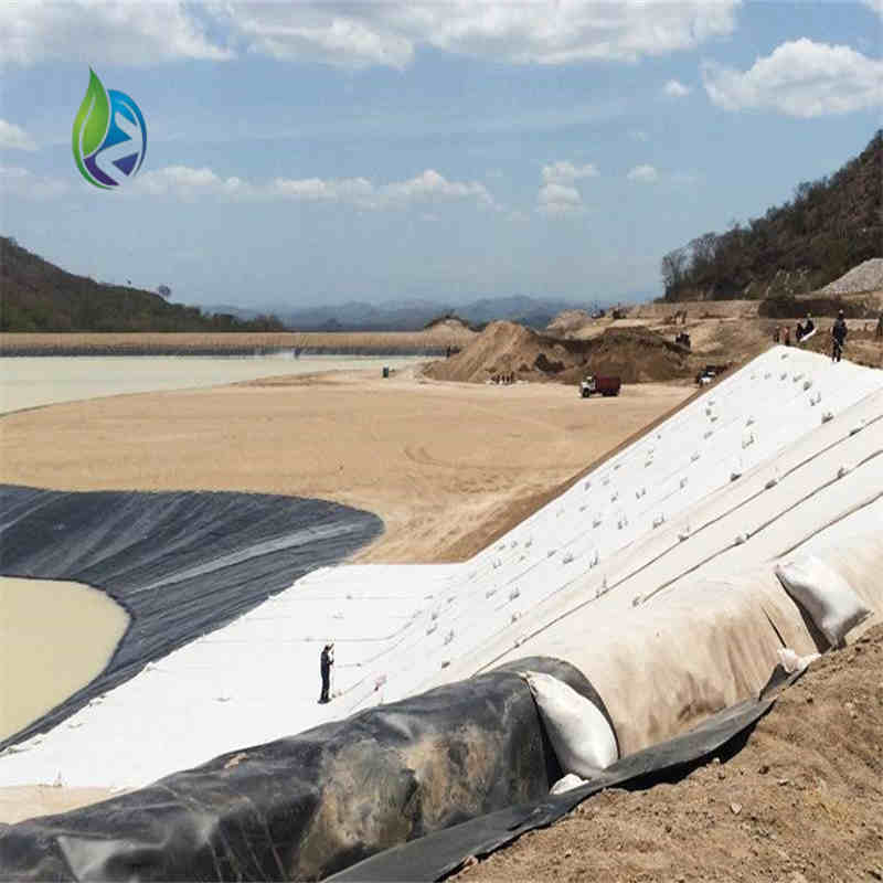
Engineering Case Example
In a regional hazardous waste landfill project, a 5.0 kg/m² Bentonite Clay Liner was installed across approximately 38,000 m² as a secondary containment layer. The system was placed over compacted subgrade and protected by a drainage composite, achieving long-term permeability compliance under enforced regulatory audits.
FAQ
Q1: What is the typical overlap width during installation?
A: 150–300 mm.Q2: Can it be installed in cold climates?
A: Yes, when handled and stored properly.Q3: Is hydration required before backfilling?
A: No, hydration occurs naturally after placement.Q4: Can it replace compacted clay liners?
A: Yes, in many engineered designs.Q5: What is the typical roll width?
A: 4–5 meters.Q6: How is quality verified on site?
A: By checking mass per unit area and visual inspection.Q7: Does it require welding like HDPE liners?
A: No, overlaps rely on bentonite swelling.Q8: Can it be combined with geomembranes?
A: Yes, as part of composite liner systems.Q9: What subgrade preparation is required?
A: Smooth, compacted, and free of sharp objects.Q10: Is it resistant to roots and biological intrusion?
A: Yes, under standard buried conditions.
CTA – Commercial Technical Request
For project procurement, submit formal requests for quotation, detailed technical documentation, and engineering-grade samples of Bentonite Clay Liner through qualified technical sales representatives.
E-E-A-T Author Credentials
This content is prepared by experienced geotechnical and environmental engineering specialists with more than 15 years of professional practice in geosynthetics design, containment engineering, and EPC technical advisory services for large-scale infrastructure and environmental projects.