
Rough Geomembrane
Manufacturing Process
Raw Material Preparation: Polymer resin blending with carbon black and stabilizers
Flat Die or Blown Film Extrusion: Formation of continuous geomembrane sheet
Texturing Process: Inline embossing or nitrogen gas injection to create rough surface
Thickness and Surface Control: Laser or sensor-based real-time monitoring
Cooling and Annealing: Dimensional stability enhancement
Quality Inspection: Mechanical testing, friction angle verification, visual checks
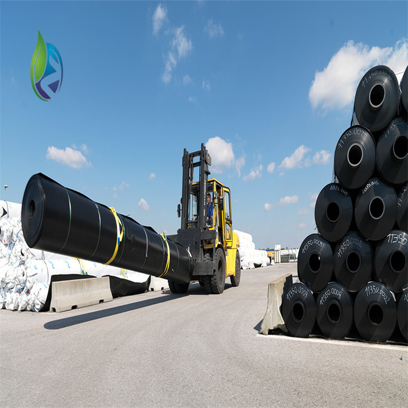
Rolling and Packaging: Protective wrapping for transportation and storage
Product Definition
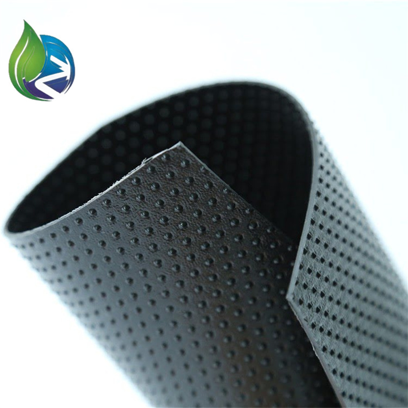
Rough Geomembrane is a textured polymeric impermeable liner engineered to enhance interface friction between lining systems and adjacent soils or geosynthetics, widely used in slope lining, landfill containment, and hydraulic engineering where stability and anti-sliding performance are critical.
Technical Parameters and Specifications
Material type: HDPE / LLDPE
Surface type: Single-sided rough / Double-sided rough
Nominal thickness: 0.75 mm – 3.0 mm
Sheet width: 5.8 m – 8.0 m
Sheet length: 50 m – 200 m (customizable)
Density (HDPE): ≥0.94 g/cm³
Textured asperity height: 0.25 – 0.50 mm
Interface friction angle: 22° – 34° (material dependent)
Tensile strength at yield: ≥15 MPa
Elongation at break: ≥700%
Carbon black content: 2.0% – 3.0%
Service life (buried): ≥50 years
Structure and Material Composition
Base Polymer Layer: High-density or linear low-density polyethylene providing impermeability
Textured Surface Layer: Engineered roughness formed during extrusion or embossing
Carbon Black Additives: UV resistance and long-term durability
Stabilizers and Antioxidants: Protection against thermal and oxidative aging
Optional Reinforcement Interface: Designed to work with geotextiles or drainage layers
Manufacturing Process
Raw Material Preparation: Polymer resin blending with carbon black and stabilizers
Flat Die or Blown Film Extrusion: Formation of continuous geomembrane sheet
Texturing Process: Inline embossing or nitrogen gas injection to create rough surface
Thickness and Surface Control: Laser or sensor-based real-time monitoring
Cooling and Annealing: Dimensional stability enhancement
Quality Inspection: Mechanical testing, friction angle verification, visual checks
Rolling and Packaging: Protective wrapping for transportation and storage
Industry Comparison
| Parameter | Rough Geomembrane | Smooth Geomembrane | Clay Liner |
|---|---|---|---|
| Interface Friction | High (anti-slip) | Low | Moderate |
| Slope Stability | Excellent | Limited | Variable |
| Impermeability | Excellent | Excellent | Moderate |
| Construction Control | High consistency | High consistency | Highly dependent on workmanship |
| Long-Term Performance | Stable | Stable | Prone to cracking |
Application Scenarios
Landfill base liners and steep side slopes
Heap leach pads in mining projects
Reservoirs, canals, and water containment slopes
Tailings dams and industrial waste ponds
EPC environmental protection projects
Core Pain Points and Solutions
Slope liner slippage: Rough Geomembrane increases frictional resistance
Interface instability under load: Textured surface improves shear strength
Complex anchoring design: Reduced need for excessive anchoring systems
Long-term safety concerns: Durable polymers ensure stable performance over decades
Risk Warnings and Mitigation Measures
Incorrect friction angle assumptions may cause design errors; use tested values
Surface damage during installation; enforce strict handling protocols
Improper welding parameters; require qualified welding technicians
Extended UV exposure before cover; minimize outdoor storage duration
Procurement and Selection Guide
Define slope angle and stability requirements
Select single-sided or double-sided roughness based on interface conditions
Determine appropriate thickness according to mechanical load
Verify friction angle test reports from accredited laboratories
Confirm compliance with relevant ASTM or ISO standards
Evaluate manufacturer production capability and project references
Engineering Case Study
In a hazardous waste landfill project with 1V:2H side slopes, a 2.0 mm double-sided Rough Geomembrane was installed over a compacted clay liner. Interface shear testing and field monitoring showed a safety factor improvement of over 35%, while maintaining long-term liner integrity under waste loading conditions.
FAQ
What is the main advantage of Rough Geomembrane? — Enhanced interface friction.
Is it suitable for steep slopes? — Yes, especially where sliding risk exists.
Single or double rough, how to choose? — Based on contact layers above and below.
Does roughness affect welding? — No, welding is performed on smooth edges.
What thickness is common for landfills? — Typically 1.5–2.5 mm.
Can it be combined with geotextile? — Yes, commonly used together.
How is quality verified? — Mechanical and interface shear testing.
What standards apply? — ASTM GRI-GM13 or equivalent.
Is installation equipment different from smooth liners? — No major difference.
What is the expected service life? — Over 50 years in buried conditions.
Call to Action
For technical datasheets, interface friction test results, project-specific recommendations, or commercial quotations for Rough Geomembrane, please submit your engineering requirements to receive a professional response.
E-E-A-T Author Credentials
This article is authored by geosynthetics engineers with over 15 years of experience in environmental containment systems, landfill engineering, and hydraulic infrastructure projects, supporting EPC contractors and material procurement teams globally.