Blind Drainage Ditch
Technical Parameters and Specifications
Blind drainage ditch performance depends on hydraulic capacity, material compatibility, and installation accuracy. Typical technical parameters are defined according to project drainage requirements.
Trench width: 300–1200 mm
Trench depth: 500–3000 mm
Perforated pipe diameter: DN100–DN300
Pipe material: HDPE or PVC-U
Aggregate size: 20–50 mm crushed stone
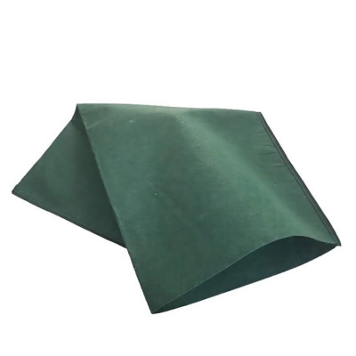
Geotextile type: Nonwoven PP, 200–400 g/m²
Hydraulic gradient: ≥0.3%
Design discharge capacity: Determined by Darcy-based flow calculation
Service life: 25–50 years (with proper filtration design)
Product Definition
A blind drainage ditch is a subsurface drainage structure designed to collect and discharge groundwater without an open surface channel. It typically consists of graded aggregates, geotextiles, and perforated pipes, providing efficient drainage, soil stabilization, and long-term water control in civil and infrastructure engineering projects.
Technical Parameters and Specifications
Blind drainage ditch performance depends on hydraulic capacity, material compatibility, and installation accuracy. Typical technical parameters are defined according to project drainage requirements.
Trench width: 300–1200 mm
Trench depth: 500–3000 mm
Perforated pipe diameter: DN100–DN300
Pipe material: HDPE or PVC-U
Aggregate size: 20–50 mm crushed stone
Geotextile type: Nonwoven PP, 200–400 g/m²
Hydraulic gradient: ≥0.3%
Design discharge capacity: Determined by Darcy-based flow calculation
Service life: 25–50 years (with proper filtration design)
Structure and Material Composition
A blind drainage ditch is a composite drainage system integrating filtration, conveyance, and soil separation functions.
Surface backfill layer: Native soil or engineered fill
Filter geotextile wrap: Prevents soil particle migration
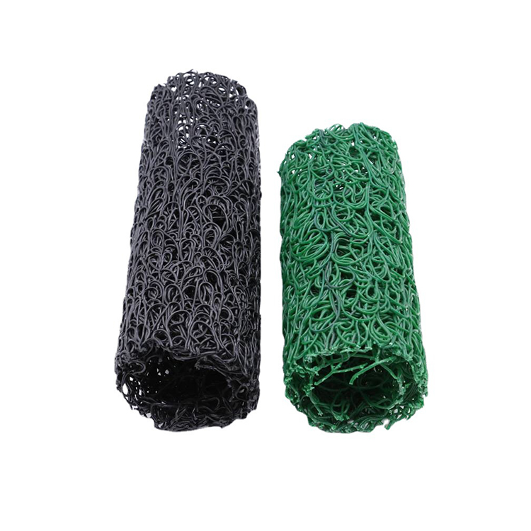
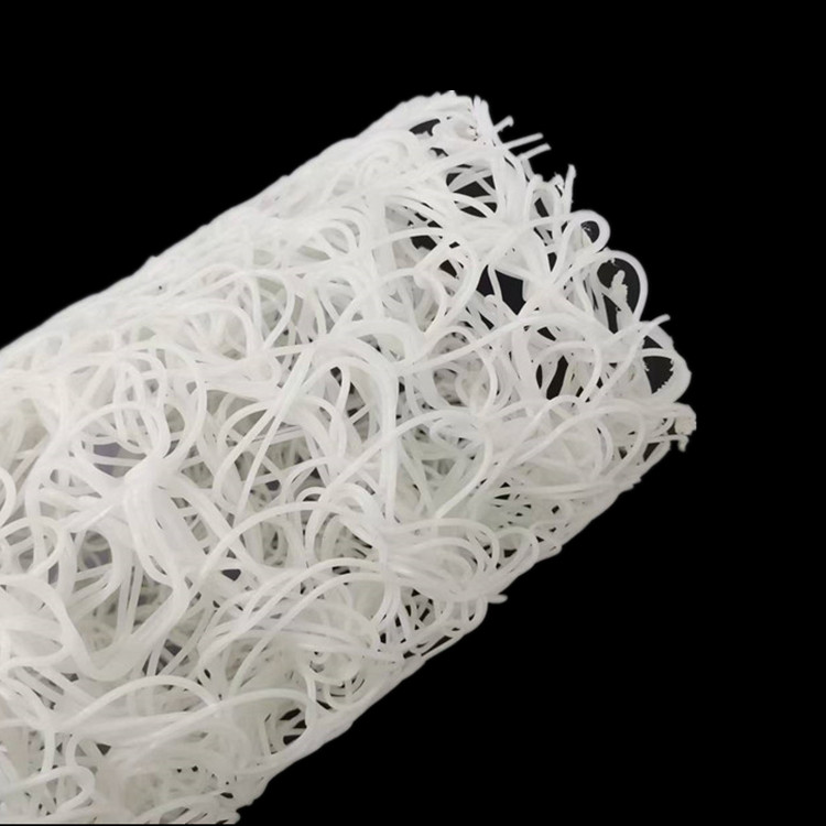
Gravel drainage layer: Provides void space for water flow
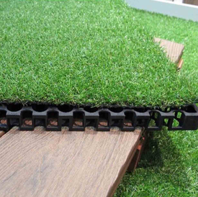
Perforated drainage pipe: Collects and conveys groundwater
Trench base: Leveled and compacted foundation
Manufacturing and Construction Process
Engineering-Oriented Implementation Steps
Hydrogeological assessment and drainage layout design
Trench excavation with controlled slope and alignment
Foundation leveling and base preparation
Placement of geotextile liner along trench walls
Installation of perforated drainage pipe with gradient control
Layered placement of graded aggregates
Geotextile wrapping and overlap sealing
Backfilling and surface restoration
Key equipment: Excavators, laser levels, compaction equipment, pipe alignment tools.
Process control points: Pipe slope accuracy, aggregate cleanliness, and geotextile continuity.
Industry Comparison
| Drainage Solution | Surface Impact | Hydraulic Efficiency | Maintenance Demand | Application Scope |
|---|---|---|---|---|
| Blind Drainage Ditch | Very Low | High | Low | Infrastructure, Slopes |
| Open Drainage Ditch | High | Medium | High | Rural, Temporary Works |
| Surface Channel | High | Medium | Medium | Roadside Drainage |
| Drainage Board System | Low | Medium | Low | Basements, Retaining Walls |
Application Scenarios
Blind drainage ditch systems are widely adopted in projects where surface drainage is impractical or undesirable.
Highway and railway subgrades: Control groundwater and prevent frost heave
Slope stabilization works: Reduce pore water pressure
Retaining walls: Relieve hydrostatic pressure
Industrial platforms: Subsurface water management
EPC infrastructure projects: Integrated drainage solutions
Core Pain Points and Engineering Solutions
Hidden groundwater accumulation: Blind drainage provides continuous subsurface flow paths
Soil erosion and piping: Proper filtration design prevents fines migration
Limited surface space: Subsurface installation preserves usable land area
Long-term clogging risk: Graded aggregates and geotextiles extend service life
Risk Warnings and Mitigation Recommendations
Incorrect filter design may cause geotextile clogging
Insufficient slope can reduce drainage efficiency
Poor aggregate quality may introduce fines
Improper pipe joints can lead to sediment ingress
Procurement and Selection Guide
Conduct site-specific hydrogeological analysis
Define required drainage capacity and spacing
Select pipe diameter and perforation pattern
Specify geotextile filtration and strength criteria
Determine aggregate gradation and cleanliness
Ensure compliance with local drainage standards
Evaluate supplier technical support and references
Engineering Case Example
In a highway slope stabilization project, blind drainage ditches were installed behind retaining structures using DN160 perforated HDPE pipes wrapped in 300 g/m² nonwoven geotextile. The system effectively reduced groundwater pressure, minimized slope deformation, and eliminated surface drainage channels, improving long-term operational safety.
FAQ
What is the main function of a blind drainage ditch? Subsurface groundwater collection and discharge.
Does it require surface maintenance? Minimal compared to open ditches.
Is geotextile always required? Yes, for filtration and separation.
Can it be used in clay soils? Yes, with proper filter design.
What pipe material is recommended? HDPE or PVC-U.
How deep can blind drainage ditches be installed? Typically up to 3 m.
Is it suitable for heavy traffic areas? Yes, when properly backfilled.
How is clogging prevented? Through graded aggregates and geotextiles.
Can it replace open ditches? In many engineered applications, yes.
Is hydraulic calculation required? Yes, for engineering-grade projects.
CTA
For blind drainage ditch design drawings, technical specifications, material recommendations, or project-based quotations, please submit a formal request for engineering consultation or product documentation.
E-E-A-T Author Credentials
This article is authored by a geotechnical and drainage engineering specialist with over 15 years of experience in subsurface drainage systems for transportation infrastructure, slope stabilization, and large-scale EPC civil engineering projects.