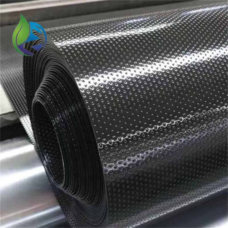
Textured HDPE Geomembrane
Manufacturing Process
Textured HDPE Geomembrane is produced using controlled extrusion and surface modification processes.
Virgin HDPE resin inspection and formulation
High-temperature flat-die extrusion
Inline or post-extrusion texturing using nitrogen injection or embossing technology
Automated thickness and surface roughness monitoring
Controlled cooling to lock surface texture
Roll winding under controlled tension
Mechanical, physical, and durability testing
Product Definition
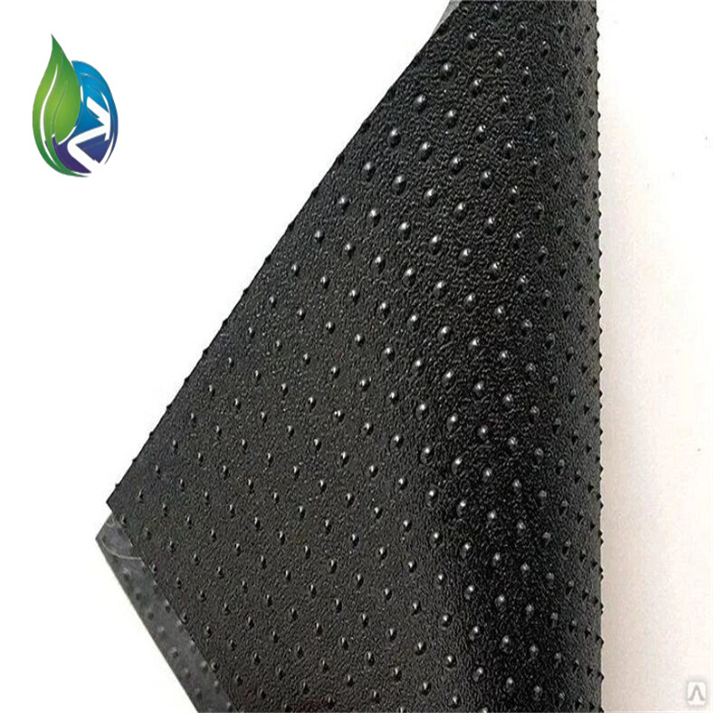
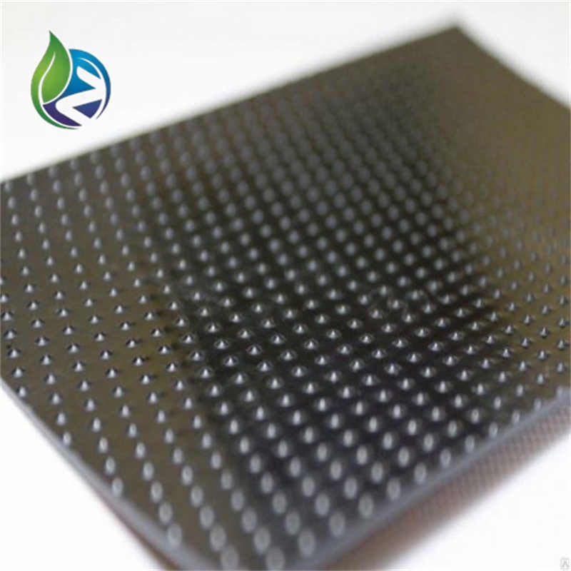
Textured HDPE Geomembrane is a high-density polyethylene impermeable liner with engineered surface roughness on one or both sides, designed to increase interface friction and slope stability in containment and lining systems used in demanding civil and environmental engineering projects.
Technical Parameters and Specifications
Textured HDPE Geomembrane is manufactured to meet internationally recognized geomembrane performance standards for high-risk containment applications.
Thickness Range: 1.0 mm – 3.0 mm
Density: ≥ 0.940 g/cm³
Tensile Strength at Yield: ≥ 15 MPa
Tensile Strength at Break: ≥ 20 MPa
Elongation at Break: ≥ 700%
Puncture Resistance: ≥ 500 N
Tear Resistance: ≥ 250 N
Carbon Black Content: 2.0% – 3.0%
Oxidative Induction Time (Standard OIT): ≥ 100 minutes
Oxidative Induction Time (High Pressure OIT): ≥ 400 minutes
Service Temperature Range: -40°C to +60°C
Standard Roll Width: 5.8 m – 7.0 m
Surface Texture Type: Single-sided or double-sided
Structure and Material Composition
The structural design of Textured HDPE Geomembrane combines mechanical strength with enhanced interfacial friction.
HDPE Base Resin: Virgin high-density polyethylene for high stiffness and chemical resistance
Textured Surface Layer: Engineered asperities to increase friction angle
Carbon Black: UV protection and long-term aging resistance
Antioxidant Package: Improves thermal and oxidative stability
Manufacturing Process
Textured HDPE Geomembrane is produced using controlled extrusion and surface modification processes.
Virgin HDPE resin inspection and formulation
High-temperature flat-die extrusion
Inline or post-extrusion texturing using nitrogen injection or embossing technology
Automated thickness and surface roughness monitoring
Controlled cooling to lock surface texture
Roll winding under controlled tension
Mechanical, physical, and durability testing
Industry Comparison
| Material | Surface Friction | Chemical Resistance | Slope Stability | Relative Cost | Typical Application |
|---|---|---|---|---|---|
| Textured HDPE Geomembrane | Very High | Excellent | Excellent | Medium-High | Landfill slopes, heap leach pads |
| Smooth HDPE Geomembrane | Low | Excellent | Moderate | Medium | Flat containment areas |
| Textured LLDPE Geomembrane | High | Good | High | Medium | Irregular subgrades |
| PVC Geomembrane | Moderate | Moderate | Low | Low-Medium | Light-duty lining |
Application Scenarios
Textured HDPE Geomembrane is specified by EPC contractors, engineering consultants, and distributors for:
Municipal and hazardous waste landfill slopes
Mining heap leach pads and tailings facilities
Steep-sided wastewater treatment lagoons
Secondary containment for industrial tanks
Earth dam upstream and downstream lining
High-risk containment systems requiring shear resistance
Core Engineering Pain Points and Solutions
Interface sliding on slopes: Textured surface increases friction angle
Liner instability under load: High tensile strength resists deformation
Chemical exposure: HDPE provides excellent chemical resistance
Long-term aging: Antioxidant-stabilized formulation extends service life
Risk Warnings and Mitigation Recommendations
Ensure compatibility testing with adjacent geosynthetics
Control welding temperature to avoid damaging textured surface
Perform interface shear testing for critical slope designs
Avoid excessive dragging that may flatten surface texture
Implement rigorous QA/QC during installation
Procurement and Selection Guide
Define slope angle and stability requirements
Select single-sided or double-sided texture based on interface conditions
Determine thickness according to load and regulatory standards
Verify compliance with GRI GM13 or equivalent specifications
Request interface friction and shear test data
Evaluate supplier manufacturing technology and consistency
Plan installation and quality assurance procedures
Engineering Case Application
In a mining heap leach project, a 2.0 mm double-sided Textured HDPE Geomembrane was installed on a 3H:1V slope beneath a geotextile protection layer. Interface shear testing confirmed adequate stability, and the system has maintained liner integrity under sustained ore loading.
Frequently Asked Questions (FAQ)
What is the main advantage of textured HDPE? — Improved slope stability.
Is it suitable for flat areas? — Yes, but often unnecessary.
Can it be welded like smooth HDPE? — Yes, with proper parameter control.
What texture types are available? — Single-sided and double-sided.
Does texture reduce chemical resistance? — No.
What thickness is common for landfills? — Typically 1.5–2.5 mm.
Is interface shear testing required? — Recommended for slope designs.
Does texture affect service life? — No, if properly stabilized.
Can it be used with geotextiles? — Yes, commonly.
What standards apply? — GRI GM13 and relevant ASTM tests.
Call to Action
For project-specific quotations, detailed technical datasheets, interface shear test reports, or engineering samples of Textured HDPE Geomembrane, please submit your project parameters to our technical sales and engineering team.
E-E-A-T Author Credentials
This article is authored by a senior geosynthetics engineer with over 15 years of experience in HDPE geomembrane design, manufacturing quality control, and EPC project support for landfill, mining, and infrastructure applications worldwide.