Reinforcement Geogrid
Manufacturing Process
Industrial manufacturing workflow of Reinforcement Geogrid:
Polymer resin drying and melt filtration
Sheet extrusion or tape stretching forming continuous base material
Precision punching or molding to create aperture patterns
Controlled biaxial or uniaxial stretching to orient molecular chains
Thermal setting to lock in tensile properties
Online tensile and dimensional quality testing
Roll forming, labeling and batch packaging
Product Definition
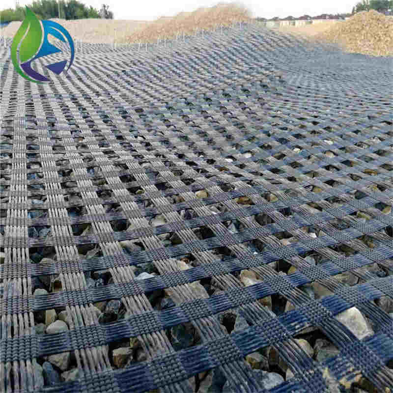
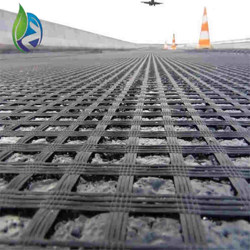
Reinforcement Geogrid is a high-strength polymer grid structure used to improve the mechanical performance of soil and aggregate layers by interlocking, load distribution and tensile reinforcement, widely applied in road subgrades, retaining walls and slope stabilization systems.
Technical Parameters and Specifications
Typical engineering parameters of Reinforcement Geogrid used in infrastructure projects:
Polymer type: High-density polyethylene (HDPE), polypropylene (PP) or polyester (PET)
Tensile strength (MD/TD): 20–250 kN/m
Junction efficiency: ≥ 90%
Elongation at maximum load: ≤ 12%
Aperture size: 25 × 25 mm to 65 × 65 mm
Creep reduction factor: ≥ 1.4 (design life 50 years)
UV resistance: ≥ 70% retained strength after 500 hours exposure
Chemical resistance: Stable in pH 3–11 environments
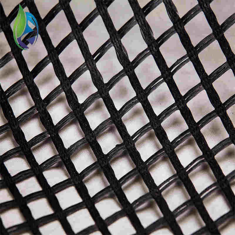
Structure and Material Composition
Typical structural configuration of Reinforcement Geogrid:
Orthogonal rib network for biaxial load transfer
Node junctions engineered for high shear resistance
Surface texturing or perforation for soil interlock
Material composition:
HDPE or PP base resin
Carbon black as UV stabilizer
Antioxidant and thermal stabilizer additives
Manufacturing Process
Industrial manufacturing workflow of Reinforcement Geogrid:
Polymer resin drying and melt filtration
Sheet extrusion or tape stretching forming continuous base material
Precision punching or molding to create aperture patterns
Controlled biaxial or uniaxial stretching to orient molecular chains
Thermal setting to lock in tensile properties
Online tensile and dimensional quality testing
Roll forming, labeling and batch packaging
Industry Comparison
| Material Type | Tensile Performance | Creep Resistance | Installation Efficiency | Service Life |
|---|---|---|---|---|
| Reinforcement Geogrid | Very High | High | Fast | 50+ Years |
| Geotextile Fabric | Medium | Medium | Fast | 25–40 Years |
| Steel Wire Mesh | High | Low (Corrosion Risk) | Slow | 15–25 Years |
| Traditional Aggregate Layer | Low | Low | Slow | 10–20 Years |
Application Scenarios
Reinforcement Geogrid is widely specified by distributors and EPC contractors for:
Highway and airport runway base reinforcement
Railway ballast stabilization
Retaining wall and reinforced soil wall construction
Soft soil foundation improvement
Industrial yard and port pavement stabilization
Key Pain Points and Solutions
Excessive subgrade settlement: Tensile reinforcement redistributes vertical loads.
Lateral soil movement: Rib and node system provides strong confinement.
Cracking of pavement layers: Interlock mechanism reduces shear displacement.
Uneven compaction quality: Geogrid provides consistent structural layer behavior.
Risk Warnings and Mitigation Recommendations
Risk of incorrect orientation; install according to marked principal strength direction.
Risk of UV exposure degradation; limit outdoor storage time before installation.
Risk of poor node engagement; avoid over-stretching during laying.
Risk of chemical attack in extreme environments; verify compatibility with site soil chemistry.
Procurement and Selection Guide
Confirm design tensile requirements and safety factors from geotechnical report.
Determine uniaxial or biaxial structure based on load directionality.
Select aperture size compatible with aggregate gradation.
Request long-term creep test data and durability reports.
Verify production quality certification and traceability system.
Evaluate logistics packaging for shipment and on-site handling efficiency.
Check reference projects and field performance history.
Engineering Case Example
In a highway embankment project over soft clay, a biaxial Reinforcement Geogrid with tensile strength of 80 kN/m was installed between compacted aggregate layers. Plate load testing confirmed a significant increase in bearing capacity and a reduction in post-construction settlement during the monitoring period.
FAQ
Q1: What is the typical tensile range?
A: 20–250 kN/m.Q2: Can Reinforcement Geogrid be cut on site?
A: Yes, using standard tools.Q3: Is biaxial or uniaxial better?
A: Depends on load direction.Q4: Does it replace traditional thick base layers?
A: It can reduce required thickness.Q5: How is junction efficiency tested?
A: Laboratory node shear tests.Q6: Is it resistant to microorganisms?
A: Yes, it is biologically inert.Q7: Can it be used underwater?
A: Yes, with appropriate installation control.Q8: What is standard roll width?
A: Typically 3.95–6.0 m.Q9: How is long-term creep evaluated?
A: Accelerated creep rupture testing.Q10: Is certification required?
A: Third-party test certification is recommended.
CTA
For project quotation, technical datasheets and engineering samples of Reinforcement Geogrid, submit your project parameters to obtain formal technical and commercial support.
E-E-A-T Author Credentials
This article is authored by a geotechnical materials engineer with more than 15 years of experience in soil reinforcement system design, laboratory testing and EPC infrastructure material specification.